4 Watt FM Transmitter
4 Watt FM Transmitter

General Description
This is a small but quite powerful FM transmitter having three RF stages incorporating an audio preamplifier for better modulation. It has an output power of 4 Watts and works off 12-18 VDC which makes it easily portable. It is the ideal project for the beginner who wishes to get started in the fascinating world of FM broadcasting and wants a good basic circuit to experiment with.
 Labels:

3-3.5 Watt FM Transmitter
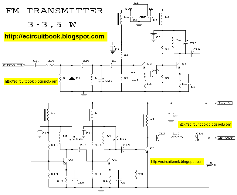
This is the schematic for an FM transmitter with 3 to 3.5 W output power that can be used between 90 and 110 MHz. Although the stability isn't so bad, a PLL can be used on this circuit.

FMTransmitter_2

Colpitts oscillator. Its frequency depends on the capacitance of the vary cap diode. The center frequency is changed by varying the biasing voltage of the vary cap through the 47K pot. You can use a 75cm telescopic antenna or simply a length of hook-up wire. Mine worked fine with a 6cm hook-up wire and gave a range of 100m with a good FM receiver. The approx. cost of the circuit is around Rs.35
FM Broadcast Transmitter

This circuit will transmit a continuous audio tone on the FM broadcast band (88-108 MHz) which could used for remote control or security purposes. Circuit draws about 30 mA from a 6-9 volt battery and can be received to about 100 yards. A 555 timer is used to produce the tone (about 600 Hz) which frequency modulates a Hartley oscillator. A second JFET transistor buffer stage is used to isolate the oscillator from the antenna so that the antenna position and length has less effect on the frequency.
Small FM Transmitter_2
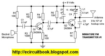
Transmitter Parts:
R1, R4, R6 10K resistor
R2 1Meg resistor
R3 100K resistor
R5 100 ohm resistor
R7 1K resistor
C1, C2 0.1uf capacitor
C3 0.01uf capacitor
C4 4-40pf variable capacitor
C5 4.7pf capacitor
Q1, Q2 2N3904 transistor
L1 8-10 turns of 22gauge wire around non-conductive 1/4" diameter form
Elec Mike Electret Mic
Small FM Transmitter
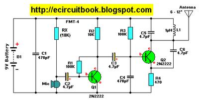
Parts List:
R1,R3 = 100K
R2 = 10K
R4 = 470 ohm
C1,C4 = 470pF
C2,C3 = 4.7µF, 16V, electrolytic
C5,C6 = 4.7pF
C7 = 4-40pF trimmer cap (optional, see text)
L1 = 1µH
Q1,Q2 = 2N2222, NPN transistor
Mic = Electret Microphone
B1 = 9 Volt, Alkaline battery
Dome light dimmer for Cars

This unique circuit makes your dome light look cool. Usually when the car door is closed, the dome light just goes OFF. With this circuit, you can have our dome light fade slowly in brightness and finally go OFF. This slow dimming of the light gives a very good feeling at night. It looks very romantic!
Wiper Speed Control

A continuously working wiper in a car may prove to be a nuisance, especially when it is not raining heavily. By using the circuit described here one can vary sweeping rate of the wiper from once a second to once in ten seconds. The circuit comprises two timer NE555 ICs, one CD4017 decade counter, one TIP32 driver transistor, a 2N3055 power transistor (or TIP3055) and a few other discrete components. Timer IC1 is configured as a mono- stable multivibrator which produces a pulse when one presses switch S1 momentarily. This pulse acts as a clock pulse for the decade counter (IC2) which advances by one count on each successive clock pulse or the push of switch S1. Ten presets (VR1 through VR10), set for different values by trial and error, are used at the ten outputs of IC2. But since only one output of IC2 is high at a time, only one preset (at selected output) effectively comes in series with timing resistors R4 and R5 connected in the circuit of timer IC3 which functions in astable mode. As presets VR1 through VR10 are set for different values, different time periods (or frequencies) for astable multivibrator IC3 can be selected. The output of IC3 is applied to pnp driver transistor T1 (TIP32) for driving the final power transistor T2 (2N3055) which in turn drives the wiper motor at the selected sweep speed. The power supply for the wiper motor as well as the circuit is tapped from the vehicle�s battery itself. The duration of monostable multivibrator IC1 is set for a nearly one second period
Charge Monitor for 12V lead acid battery

A battery is a vital element of any battery-backed system. In many cases the battery is more expensive than the system it is backing up. Hence we need to adopt all practical measures to conserve battery life.
As per manufacturer's data sheets, a 12V rechargeable lead-acid battery should be operated within 10. IV and 13.8V.
Audio level meter (vumeter)

This circuit uses just one IC and a very few number of external components. It displays the audio level in terms of 10 LEDs. The input voltage can vary from 12V to 20V, but suggested voltage is 12V.The LM3915 is a monolithic integrated circuit that senses analog voltage levels and drives ten LEDs providing a logarithmic 3 dB/step analog display. LED current drive is regulated and programmable, eliminating the need for current limiting resistors.The IC contains an adjustable voltage reference and an accurate ten-step voltage divider. The high-impedance input buffer accepts signals down to ground and up to within 1.5V of the positive supply. Further, it needs no protection against inputs of 35V. The input buffer drives 10 individual comparators referenced to the precision divider. Accuracy is typically better than 1 dB.
Bass-treble tone control circuit
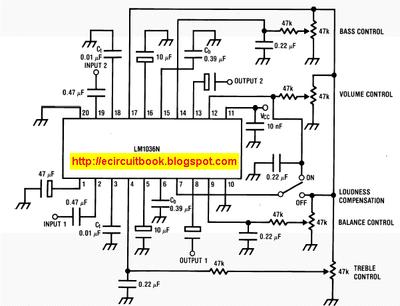
The LM1036 is a DC controlled tone (bass/treble), volume and balance circuit for stereo applications in car radio, TV and audio systems. An additional control input allows loudness compensation to be simply effected. Four control inputs provide control of the bass, treble, balance and volume functions through application of DC voltages from a remote control system or, alternatively, from four potentiometers which may be biased from a zener regulated supply provided on the circuit. Each tone response is defined by a single capacitor chosen to give the desired characteristic.
Audio Light Modulator

Audio light modulations add to the enjoyment of music during functions organised at home or outdoors. Presented here is one such simple circuit in which light is modulated using a small fraction of the audio output from the speaker terminals of the audio amplifier. The output from the speaker terminals of audio amplifier is connected to a transformer (output transformer used in transistor radios) through a non-polarised capacitor. The use of transformer is essential for isolating the audio source from the circuit in The sensitivity control potentiometer VR1 provided in the input to transistor T1 may be adjusted to ensure that conduction takes place only after the AF exceeds certain amplitude. This control has to be adjusted as per audio source level. The audio signal Proper earthing of the circuit is quite essential. The diode bridge provides pulsating DC output and acts as a guard circuit between the mains input and pulsating DC output. Extreme care is necessary to avoid any electric shock
5 band graphic equalizer using a single IC/chip

This circuit uses a single chip, IC BA3812L for realizing a 5 band graphic equalizer for use in hi-fi audio systems.The BA3812L is a five-point graphic equalizer that has all the required functions integrated onto one IC. The IC is comprised of the five tone control circuits and input and output buffer amplifiers. The BA3812L features low distortion, low noise, and wide dynamic range, and is an ideal choice for Hi-Fi stereo applica-tions. It also has a wide operating voltage range (3.5V to 16V), which means that it can be adapted for use with most types of stereo equipment.
Digital Volume Control

This circuit could be used for replacing your manual volume control in a stereo amplifier. In this circuit, push-to-on switch S1 controls the forward (volume increase) operation of both channels while a similar switch S2 controls reverse (volume decrease) operation of both channels.
Ultrasonic Switch
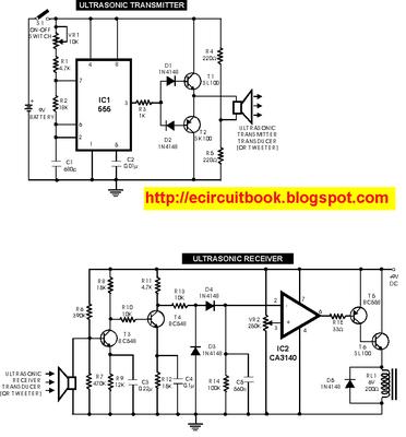
Circuit of a new type of remote control switch is described here. This circuit functions with inaudible (ultrasonic) sound. Sound of frequency up to 20 kHz is audible to human beings. The sound of frequency above 20 kHz is called ultrasonic sound. The circuit described generates (transmits) ultrasonic sound of frequency between 40 and 50 kHz.
Sound Controlled Filp Flop
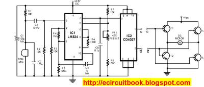
Described here is a very inexpensive solution to many phono-controlled applications like remote switching on, for instance, or activating a camera, tape recorder, burglar alarms, toys, etc. The circuit given here employs a condenser microphone as the pick-up. A two-stage amplifier built around a quad op-amp IC LM324 offers a good gain to enable sound pick-up upto four metres.
Ultrasonic pest repellent

It is well know that pests like rats, mice etc are repelled by ultrasonic frequency in the range of 30 kHz to 50 kHz. Human beings can�t hear these high-frequency sounds. Unfortunately, all pests do not react at the same ultrasonic frequency. While some pests get repelled at 35 kHz, some others get repelled at 38 to 40 kHz. Thus to increase the effectiveness, frequency of ultrasonic oscillator has to be continuously varied between certain limits.
Audio Visual Indicator for Telephones
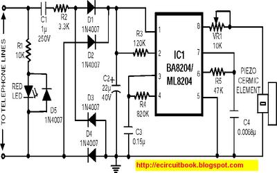
Many a times one needs an extra telephone ringer in an ad joining room to know if there is an incoming call. For example, if the telephone is installed in the drawing room you may need an extra ringer in the bedroom. All that needs to be done is to connect the given circuit in parallel with the existing telephone lines using twin flexible wires. This circuit does not require any external power source for its operation.
Use the CD-ROM drive as a audio CD player without the computer

Most of the CDROMS available have an Audio-Out Output to either plug in the headphones or connect it to an amplifier.